When we own the horizontal and vertical, we get to move, make changes, and respond to customer requirements at the pace we’re used to. We think this is a really big deal.
—James Hamilton, an AWS VP and Distinguished Engineer
Applying SAFe to Hardware Development
![]() Note: This article is part of Extended SAFe Guidance and represents official SAFe content that cannot be accessed directly from the Big Picture.
Note: This article is part of Extended SAFe Guidance and represents official SAFe content that cannot be accessed directly from the Big Picture.
Business Agility requires everyone involved in product delivery to use Lean and Agile practices to create innovative, high-quality products. As Agile adoption extends beyond software, hardware development needs to keep pace. Although the hardware community is relatively new to Agile, SAFe’s Lean-Agile Values and Principles are universal. They can be used to guide hardware engineers to create and adopt their own best practices.
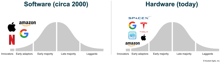
An Agile transformation will ultimately affect every part of the Enterprise. Twenty years ago, businesses struggled to deliver value to their customers due to bottlenecks in software development. Software practitioners began applying Agile practices and created new technologies such as virtualization, microservices, and infrastructure-as-code, accelerating execution and driving innovations. Today, organizations that employ these Agile practices and development innovations deliver value significantly faster with higher quality. And those early innovators now dominate the software marketplace.
Organizations building hardware systems now find themselves in a similar position. However, they can now apply the insights from the previous two decades. Many companies have already started this journey (Figure 1). Through extensive use of virtualization and learning in the digital world, General Motors cut the Hummer EV’s launch time in half [1]. This is because digital engineering shifts learning to the left by integrating virtual drawings, models, and simulations to get feedback before creating physical parts.
SpaceX uses additive manufacturing on all parts of its system, from rocket engines to helmets [2]. Additive manufacturing prints physical parts on-premises directly from computer-aided design (CAD) data, on-premises, faster than traditional manufacturing and assembly processes. Apple, Google, and Amazon also design their hardware to meet business demands [3].
Details
To create innovative, high-quality products—including those with hardware elements— business agility requires hardware participation in the SAFe transformation. The following sections describe how SAFe applies to hardware development, outlining six universal principles and how to use them.
Organize Around Value
SAFe Principle #10 – Organize Around Value, states that an organization’s value flows across its functional silos. Traditionally, work is organized around functional skills. Take, for example, a new rocket nozzle that has a mechanical structure, which is hardware (HW)—with a custom electrical circuit design, which is the firmware (FW)—and control logic to adjust the nozzle, which is software (SW). With a traditional approach, each would be developed independently, aligned by detailed specifications and a standard schedule. Verification and validation can only occur when all the components are integrated at the end, making any adjustments costly.
To enable collaboration and reduce handoffs and delays, Agile development organizes teams of cross-functional skills. Figure 2 shows three equally viable ways where this might occur and the situations in which they are optimal:

- Cross-functional Agile teams work in a highly innovative environment, with frequent experimentation and tight collaboration across all domains. Innovations in noise, electrical, and control logic design are quickly integrated and validated.
- Some innovative environments do not require the tight collaboration of a single team, and the domains can work more independently. However, to ensure their work is aligned, both teams are part of the same Agile Release Train (ART) and use SAFe practices to manage dependencies and integrate frequently.
- Other environments are more predictable. These teams can work independently on their system components, aligning their efforts with a joint Roadmap defining the critical integration points. These teams may or may not be on the same ART.
Team organization may evolve. Early product development often requires more innovation and tighter feedback (example #1 in Figure 2). Later development requires less creation and focuses on finalizing their parts for the overall product designs (examples #2 and #3 in Figure 2).
Agile teams capitalize on cross-functional skills to achieve the most value for each iteration. A mechanical engineer may make simple firmware updates, or a software engineer may modify a CAD design and rerun analysis tests. Unfortunately, many organizations incentivize deep functional skills. An Agile transformation changes these incentives to encourage broader, cross-functional skills while not sacrificing the expertise required to build innovative products.
Assume Variability and Preserve Options
Traditional engineering begins new product development by specifying a product concept in precise detail in advance and then creating a detailed schedule to build it. However, history has shown this process to be unsuccessful, particularly for innovative products with many unknowns. Agile takes a different approach.
Samuel Langley and the Wright Brothers, leading competing teams in the race for flight, provide examples of these two approaches. After showing early success with his unmanned Aerodrome, Langley was well-funded. He then devoted years to perfecting a single design, which, unfortunately, contained fundamental flaws that would prevent it from flying.
In contrast, the Wright Brothers did not set out to design an airplane. Instead, they set out to close three knowledge gaps necessary for flight: lift, control, and propulsion. They shifted learning to the left through experiments and integrated prototypes to resolve those gaps.
The Wright Brothers were perhaps the first innovation team to apply Set-Based Design. They tested repeated prototypes of subsystems (wings, rudder, elevators) that they frequently integrated with kites, gliders, and a flying machine. The integrations validated their decisions and provided fast feedback to make adjustments. They made final design decisions only after gaining sufficient knowledge and reducing the cone of uncertainty (Figure 3). For more detail, see SAFe Principle#3 – Assume variability; preserve options.

As teams create knowledge, these decisions need to be captured and managed. In SAFe, teams store and modify this information in the Solution Intent, the repository of system knowledge that includes the system’s specifications. Being agile means these specifications are not fixed; they evolve based on learning. (Figure 4) The solution roadmap defines the learning milestones that drive the exploration activities and create the knowledge necessary to build the system. Every increment of work contributes new insights for the solution intent and moves specifications from variable to fixed.

Build Incrementally, Integrate Frequently
Adhering to a fixed schedule based on phase-gate milestones in traditional development often defines success. Unfortunately, this approach forces decisions too early and can create false-positive feasibility [4]. In SAFe, milestones are based on objectively evaluating working systems (SAFe Principle #5). This requires all teams, including hardware, to frequently integrate their incremental changes into the solution.
Figure 5 contrasts the traditional approach with a continuous one. SpaceX strives to launch the next rocket version every 2-3 months to add new knowledge and data about the future solution. Learning is the goal, even when tests may seem like a failure (see Musk’s tweet in Figure 5). Instead of focusing on qualifying every component (and subassembly and assembly), SpaceX focuses on creating the infrastructure to test the next version of the solution quickly. The transaction costs for building and launching the next rocket are less than the holding costs of delayed learning. Watch [5] to see NASA’s top Administrator, Jim Bridenstine, discuss what NASA has learned from working with SpaceX.

SAFe’s roadmap and demonstrable milestones replace fixed schedules and phase-gate milestones. They define the future knowledge goals (for example, the wings can provide sufficient lift) that drive the teams’ incremental work (for example, testing multiple wing designs in the wind tunnel and validating lift with the kite), as shown in Figure 6.

Integration points control product development [4] by creating knowledge from uncertainty (SAFe Principle #4) in large system development. ARTs integrate their teams’ incremental changes so that the entire system is learning. And all teams and trains are on a common cadence, which creates natural integration points for the whole system.
Design for Change
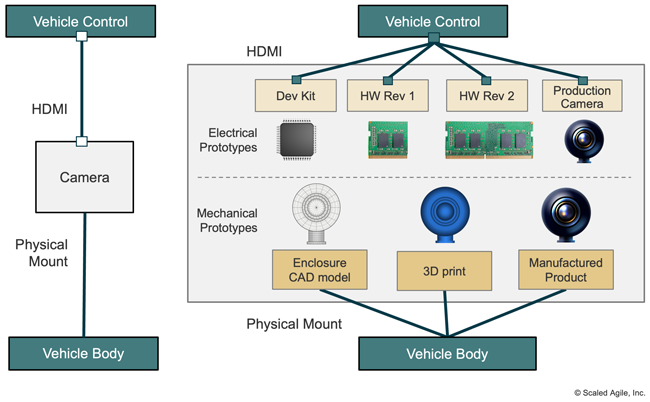
The system must reasonably and quickly change in development and operational environments to support frequent integration. Modular designs that integrate through managed interfaces enable this. For example, Figure 7 shows a camera with an electrical interface to a vehicle control unit and a physical interface with the vehicle body. These components can evolve independently if they adhere to the interface specifications. Hardware interface specifications define properties for mechanical parts (size, weight, forces exerted, mounting) and electrical components (connector type, pinouts, voltage).
While designing for change is not new, a poor understanding of economics can prevent good design decisions. For example, application-specific integrated circuit (ASIC) parts are often chosen because of their lower unit costs and power consumption. But their functionality is fixed; any change requires manufacturing and installing a new part. On the other hand, field-programmable gate arrays (FPGA) and system-on-a-chip (SOC) designs can be modified quickly and cost-effectively in both the development and operational environments. Physical joins often use solders or welds to reduce assembly costs. Non-permanent joins, like fasteners and connectors, add cost but make changes possible and more accessible. And some are now using additive manufacturing to create extensive subsystems that require no assembly. The economics must include the total costs for change and the value of evolving systems in the operational and development environments over the product’s lifetime.
Perform Work in Small Batches
Agile software teams work in the context of Stories, small, vertical slices of functionality sized to be completed in a single iteration. Hardware engineers, and most individuals new to Agile, often struggle to break down work. However, this is not debatable or optional. Breaking work into small chunks is essential for frequent integration, fast experimentation, and the ability to adapt.
Twenty years ago, the software community had this same struggle when they began their Agile journey. Over time, they created innovations (for example, microservices and API management) and tools for Continuous Integration and Continuous Deployment that simplified small batches of work. Today, most software developers can implement small, vertically-sliced stories and create working products every iteration. The hardware community is just beginning its Agile journey, which may be challenging. But in time, it will develop its practices, driving innovations and changes in its electrical and mechanical Computer-Aided Design (CAD) products that simplify small work.
Hardware developers can approach breaking work into small units of value in several ways. The first is considering the work required to reduce knowledge gaps for near-term milestones on the solution’s roadmap.
The second addresses the work of integrating changes with a more comprehensive solution. For example, instead of designing an entire circuit board or mechanical part, create a few circuits or pieces of the part. Then, find a way to combine it with other system parts for feedback by integrating models, using breadboards, or joining 3D-printed parts. Engineering labs are filled with these types of experiments. Track this kind of work in backlogs and create a proactive mindset regarding small engineering changes and verification in the larger system context. Figure 8 shows an example Kanban board of stories for the camera team discussed earlier.

Hardware teams benefit from using well-defined Stories in other ways, particularly the Definition of Ready (DoR) and Done (DoD). This is particularly true for cross-functional teams, where members may be working in a relatively new domain, unaware of all the governance practices. The DoD defines the team’s agreement on when work is complete and helps build quality.
A hardware DoD may include properly documenting data results and restoring equipment to a reusable state. The DoR is used less frequently by the Agile community and, thus, is not found in SAFe. However, it is helpful for hardware work that often depends on external items, such as equipment availability, support roles (such as only a safety engineer can approve power on), ordered material, and many others. A DoR communicates what is required to make an upcoming story actionable. The podcast in [6] describes DoR and DoD’s value to Tesla’s dynamic, cross-functional hardware teams, where iterations are measured in hours, not days.
Continuous Integration for Hardware Development
Developer changes are not verified until they can be integrated into the larger system context. Hardware development creates physical parts with material costs and long lead times. As a result, hardware verification often occurs later in the product development lifecycle, often near the end. Many strategies exist for shifting learning left at three stages of hardware development described below (Figure 9).

- Virtual World – Hardware development begins with models in design tools (for example, electrical and mechanical CAD). Many organizations now integrate virtual models to enable analysis and simulation for early feedback in a larger system context. Developers can verify their designs’ compatibility with stakeholders before manufacturing parts.
- Physical World – Some design aspects can only be verified with physical parts. Many organizations already leverage additive manufacturing and 3D printing for early feedback. They can also be used for production parts, mainly when innovation requires higher change frequency and low production volumes [1]. Reducing quality and reliability constraints on development parts can also accelerate manufacturing times. Development parts often operate in a controlled environment and are replaced by the next revision, unlike production parts which must last years in harsh environments.
- Operational World Systems must be designed to enable easy changes in the working environment. The design choices discussed earlier (FPGAs over ASICs and connectors over solder) provide examples of design choices. Allocation of system functionality to design elements also plays a critical role. As network capacity and costs enable over-the-air updates, more behavior is allocated to software and programmable components.
Continuous Integration is taking small developer changes and testing, integrating, and validating them in a context ready for delivery. In hardware development, new functionality flows from virtual designs to physical parts that are then made available for easy installation in the operational environment.
Automating continuous integration activities accelerates the flow through these environments and provides faster feedback on developer changes. The continuous integration environment is a system, too, and developers must invest the time and resources to build and make the system. As Elon Musk says, “the factory is the product.”
_________________________
Learn More
[1] SpaceX Triggers Increased Use Of 3D Printing, 2020 https://www.fabbaloo.com/blog/2020/6/9/spacex-triggers-increased-use-of-3d-printing [2] Automakers use virtual reality to reduce development time for vehicles like the Hummer EV., 2020. https://www.cnbc.com/2020/11/08/automakers-use-virtual-reality-to-cut-the-development-time-for-vehicles-like-the-hummer-ev.html [3] Why Tech Giants Like Amazon Are Designing Their Chips — And Who Benefits, 2018. https://www.thestreet.com/opinion/why-tech-giants-are-designing-their-own-chips-14807638 [4] Oosterwal, Dantar P. The Lean Machine: How Harley-Davidson Drove Top-Line Growth and Profitability with Revolutionary Lean Product Development. Amacom, 2010. [5] Exclusive interview with Elon Musk and Jim Bridenstine about #DM2, SpaceX flies astronauts for the first time, 2020. https://youtu.be/p4ZLysa9Qqg?t=266 [6] Agile at Tesla with Joe Justice. The Agile Wire Podcast, 2021. https://www.theagilewire.com/recordings/agile-at-tesla-with-joe-justice [7] Inside Elon Musk’s plan to build one starship a week. ARS Technica, 2020. https://arstechnica.com/science/2020/03/insMusk’son-musks-plan-to-build-one-starship-a-week-and-settle-mars
Last update: 6 March 2023